
 |
Camera Chassis (original model) showing the scanning / high voltage PCB side of the camera. |
 |
Camera Chassis (original model) showing the video PCB side of the camera. |
 |
Camera Chassis (original model) showing the underside of the camera. |
| 1 | Before switching on turn G1 pot RV111 anti-clockwise [clockwise] and pedestal pot RV110 clockwise [anticlockwise]. Select pan mode. Turn flicker suppressor off by setting RV212 fully anticlockwise. |
|
| 2 | Switch camera on and note current consumption, if current is greater than 500mA after the target discharge period suspect a fault. | |
| 3 | Set line flyback to 10us, measure on Q100 tag [TP103] adjust RV100. This should give a 60V clean pulse shape as shown |
 |
| 4 | Set trailing edge of blanking to lead flyback by 3˝us, measure on Q211 gate or V202 pin10 [TP111], adjust RV117. |  |
| 5 | Check G2 » 170V (Measure on D103) Check G4 » 130V (Measure on socket P108) Check G3 » 80V (TP105) Adjust using RV109. If beam and pedestal are off, initially set to 85V so it drops back to 80V Check heater voltage on P 104 pins 3 to 6 [ or across 8.7V and R200, and change R200 if required to achieve 5.9 -6.0V across the Pevicon heater.] |
|
| 6 | Open circular blanking (RV206). | |
| 7 | Set beam current to 4uA using RV111 (G1). Measure using a 3.5mm jack socket on the scan board and 50uA meter. Socket is at 130V. | |
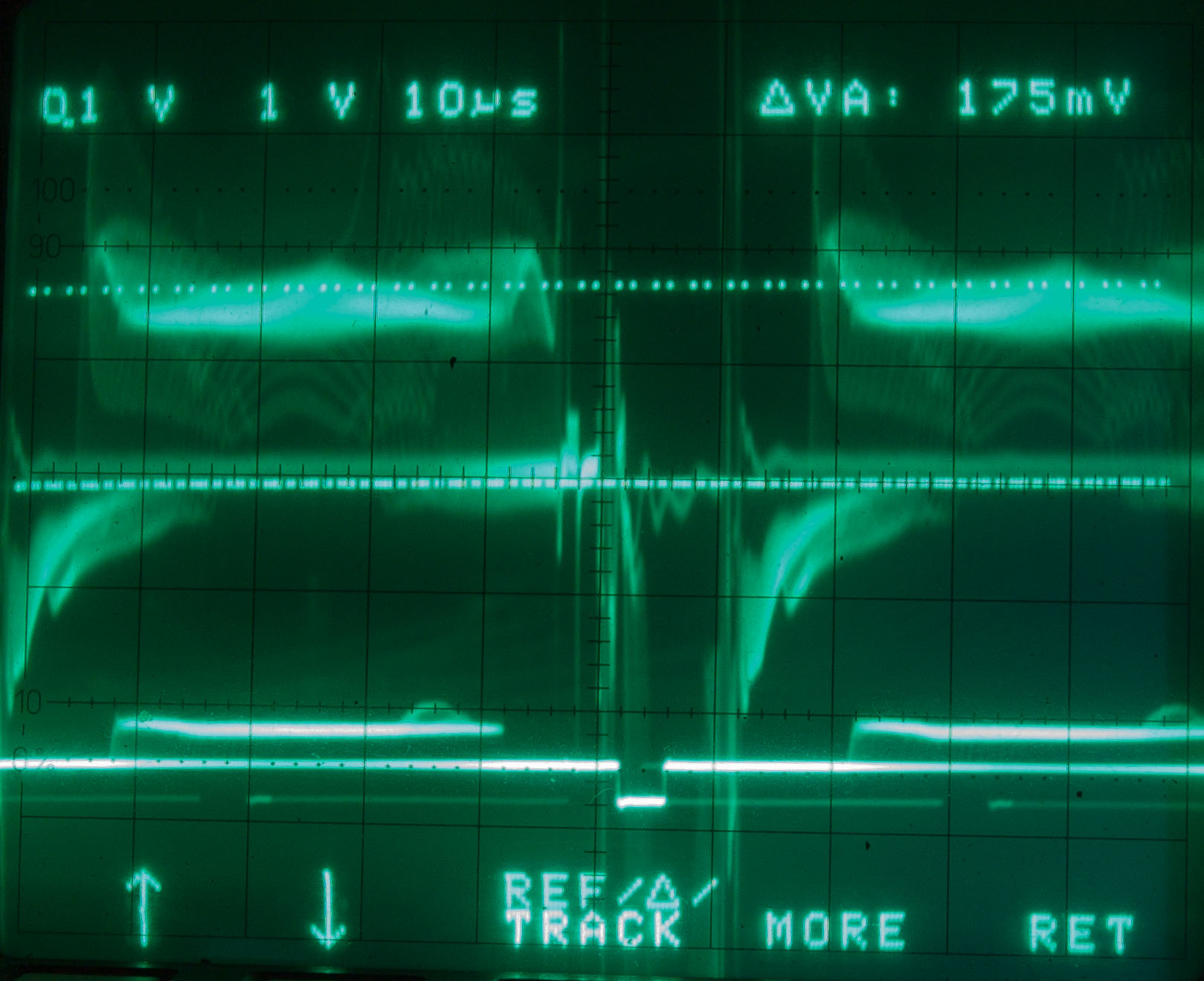
| 8 | Set pedestal by setting head amp output to 175mV measured at R219/R220 [TP6] on the video board adjust RV110 on Scan board. This will increase the beam current. |
 |
| 9 | Centralise circular image with alignments and horizontal shift controls RV102, RV103 and RV101. Set vertical amplitude of image with RV112 and horizontal amplitude with L100 [Horizontal adjustment requires change to number of turns on coil] to obtain a circular target of 38 to 42ěs width. |
|
| 10 | Focus G2 aperture spot in centre of picture using RV116. The small feature arrowed will be seen as you pass through tube electrical focus. |
 |
| 11 | Recheck the setting of G3 and items 7 to 10 above as these are interactive. | |
| 12 | Reduce circular blanking size RV206 and adjust circle shape RV207 for a circle on a monitor raster set to 3:4 ratio. The circle should be 34.7ěs wide and 15.8ms or 13.4ms high (625/525 TV systems respectively) |
|
| 13 | Check video at L201 [TP5] and adjust the shading controls to achieve as flat a signal as possible Adjust RV203, RV201 for correction at line rate. Adjust RV202, RV205 for correction at field rate. |
  |
| 14 | Switch to chop mode and set video signal to 1.3V measuring at L201 [TP5] on the video board adjusting RV204. | |
| 15 | Switch to Pan mode and set video signal to 1.3V measuring at L201 [TP5] on the video board adjusting RV200. [No longer required]. |
|
| 16 | Turn on flicker suppressor with RV212. | |
| 17 | Set period of clock pulse to 43us measured on pin 11 of V214 [pin 3 of IC13] adjusting RV209. | |
| 18 | Adjust RV212 to minimise vertical patterning. Effect may only be visible on an external monitor. | |
| 19 | Open circle (RV206) until top and bottom of stored area is visible. Centralise stored area (RV211). In the case of a 525 line camera only the top stored area will be visible, so RV211 may be set fully clockwise. Reset circle. |
 |
| 20 | Switch camera to chop mode and adjust RV210 to the centre of the range where there is no picture noise. [Switch camera to chop, no adjustment required] |
|
| 21 | Adjust RV208 to give minimum flicker. | |
| 22 | Switch to pan mode. Check "park" position of shutter blade with the black section in the shutter sensor and with the shutter clear of the tube-lens gap. Check output of sensor is approximately 3V measured at R173 [or TP113]. |
|
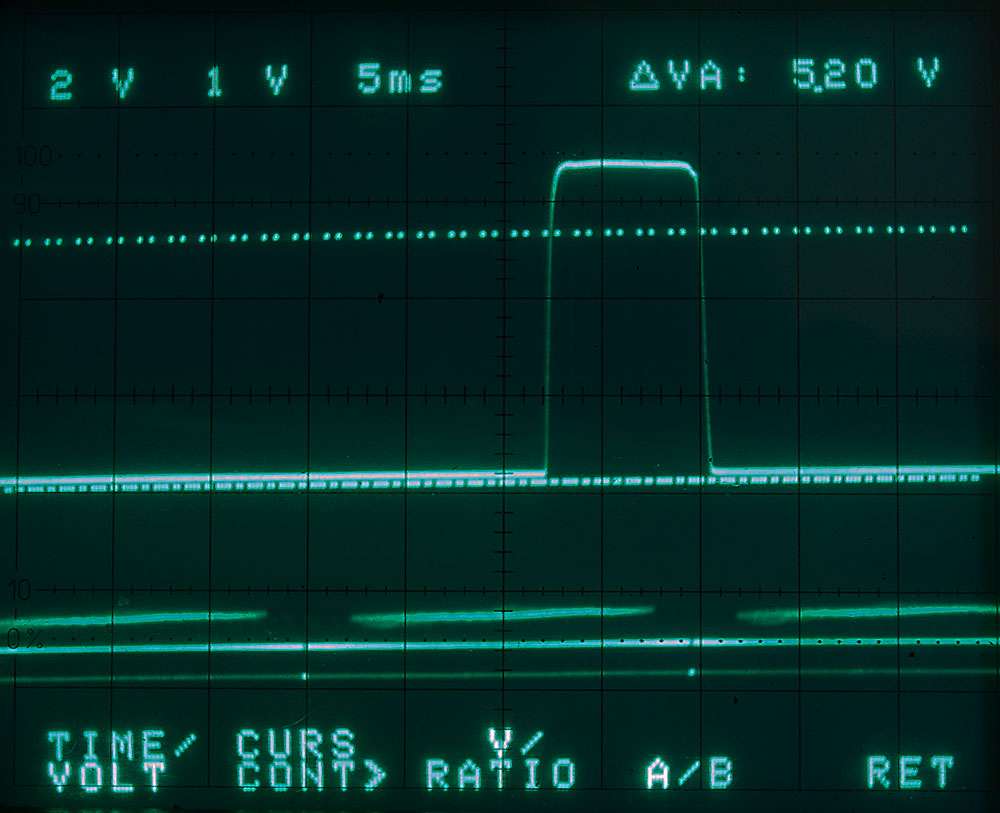
| 23 | Switch to 'chop' mode and check sensor output is locked to field rate and swings below 2V and above 6V measured at R173 [or TP113]. Select R170 for an error pulse of 0 to 2ms on V108.5 [TP112]. |
 |
| 24 | Switch to pan. Check operation of iris and adjust sensitivity using RV118. | |
| 25 | Adjust internal monitor scans and shifts (RV119, L101 RV108, RV104 and rear magnets), for a circular and central image. | |
| 26 | Adjust brightness and contrast of internal monitor (RV107 and RV106). | |
| 27 | Check and adjust optical focus by moving yoke assembly. Check yoke rotation. | |
| 28 | Check LED battery indicators. Adjust RV115 for offset and R114 for range [no adjustment]. Rail drop out point should be below 9.2V. |
|
| 29 | Check overall quality of picture and mechanical assembly. | |
 This image shows some microphony bands (arrowed) which is a tube artefact where vibrations also create a signal from the tube. With a really bad one you can shout at it. | ||