


 |
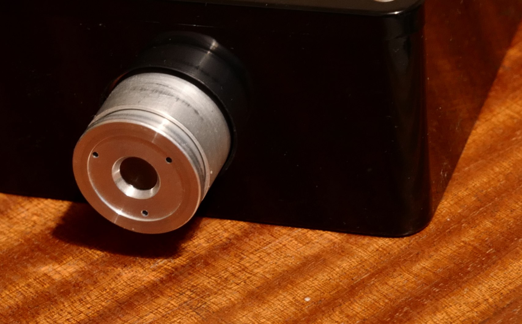
Lens. The lens can be made adjustable focus by removing the grub screw. This allows focus down to about 20mm / under 1 inch. It also makes it easier to fit into the box. In the fire camera version the lens gives a 50° field of view with an 8.5mm focal length. It is f/1 aperture. |
 |
Finished camera imaging a soldering iron. |
 |
Rear View
|
 |
Base. This view shows the core PCB set mounted in the new case with the optical block to the left. |
 |
Lid. This view shows the box lid with a video LCD mounted in it. The LCD is from Argus 3 but needed extra wiring to flip the picture round. |
Hot router and room |
|
Close ups of a soldering iron, focussed at about 25mm / 1 inch. 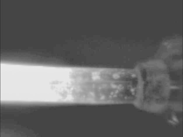 |
Of note is how this core handles very hot objects as it uses simple temperature to video brightness mapping. The soldering iron drives the rest of the room to black, until entering 'EI' mode - electronic iris, which is a low gain mode. The two sensitivities are shown in the video |
Indoors, unlit night. Shows underfloor pipe runs.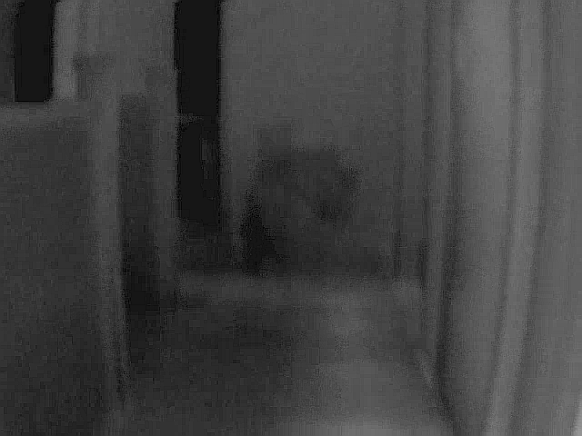 |
|
Outdoors street scene, daytime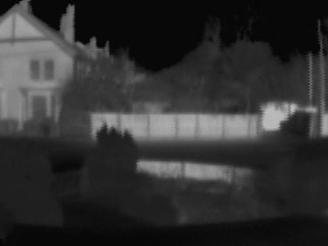 |
|
Outdoors street scene, unlit at night |
|
PCB inspection |
| Pin | Function | Notes |
| 1 | Power in + | 6 - 32V. DO NOT EXCEED 33V |
| 2 | 0V | Ground |
| 3 | Low Battery | Shows a low battery logo when grounded. Software version dependant. |
| 4 | RS485+ | |
| 5 | RS485- | |
| 6 | Ground | Ground |
| 7 | Shutter | Ground to force a manual shutter / flat field correction |
| 8 | Video Polarity | Ground to select black hot imagery |
| 9 | Low Voltage in | 2.5V - 4V an alternative to using pin 1, typically 2 x AA cells. DO NOT EXCEED 5V |
| 10 | Power Out | Connected to pin 1 via a diode to aid wiring. |
| 11 | 3.4 - 3.7V out | To drive a display, 250mA maximum |
| 12 | Video Gnd | Ground |
| 13 | Video | NTSC video |
| Pin | Function | Notes |
| 1 | Horizontal sync | optional timing |
| 2 | Vertical Sync | optional timing |
| 3 | NTSC / PAL | Pull low to force PAL, high for NTSC. Floating is auto select |
| 4 | Input select | Default composite (pin 5) Take high to force use of RGB in (pins 6,7,8). |
| 5 | Composite video in | Input video |
| 6 | Blue video in | Blue of RGB component video in |
| 7 | Red video in | Red of RGB component video in |
| 8 | Green video in | Green of RGB component video in |
| 9 | Power Ground | |
| 10 | Signal Ground | |
| 11 | DC in | 10V-13.2V |
| 12 | Signal Ground | |
| 13 | S-Video | Video input |
| 14 | LR | Ground to flip picture left-right |
| 15 | UD | Ground to flip picture top to bottom |
| Pin | Function | Notes |
| 1 | Vcc output | 5V |
| 2 | Tint | Tint adjustment 0 - 5V |
| 3 | Colour | Colour adjustment 0 - 5V |
| 4 | Brightness | Brightness adjustment 0 - 5V |
| 5 | Contrast | Contrast adjustment 0 - 5V |
| 6 | Sharpness | Sharpness adjustment 0 - 5V |
| 7 | Ground | Ground |
  |
The optical block simply contains a solenoid to operate the calibration flag, driven by the red and black wires. It is a relatively large block of aluminium mainly to reduce the rate of temperature change. The lower image shows the sensor mounted directly on the flexicable. |
  |
The first PCB, 'Processor PCB', looks like it dealt with sensor correction and has as main IC's TI TMS320VC5410 DSP and AD7472 12 bit 1.25MHz ADC and an unidentifiable clock generator IC (perhaps custom ?) |
  |
The second PCB, 'Reformatter PCB', looks like it dealt with producing the NTSC video image and has power supplies (MIC4680, LTC3401) There is a 24MHz clock, TI TMS320VC5410 DSP, and AD9708 8 bit DAC. It has the 'public' user connections of J1 and J3. |